In 1932, by introducing a four-stroke with push-rod-operated valve gear, in the motor cycle design field. The design incorporated numerous new and praiseworthy features. One of these was the high-mounted camshaft which permitted the use of short, sturdy push-rods. But perhaps more important was the fact that the valve stems and springs were totally enclosed. This feature caused widespread discussion. Many claimed that valve enclosure would prove to be a mixed blessing. Certainly, it was said, greater external cleanliness would result, and it was agreed that dust and road grit would be kept away from the valve guides. But, against these points, it was argued that the valve springs would receive inadequate cooling and, in the long run, exposed valve gear was to be preferred. How unfounded those views were has been proved beyond all doubt in the ensuing 20 years. The original engine with totally enclosed valves was of 248 c.c. capacity, and it was “square,” with a bore and stroke of 68 x 68.25 mm. Later, the stroke was increased to 96mm. To bring the capacity to 349 c.c. Thus, the MAC Velocette, a “sports” three-fifty, was born. From then on, the engine remained unchanged until June, 1951, when the top half was extensively redesigned to bring it into line with modern trends. However, the basic design remains, and in my questionnaire I decided to delve into the “reasons why” behind the illustrious original engine as well as those concerning the more recent version. Since the first World War, incidentally, Velocettes had marketed only two-strokes and overhead-camshaft four-strokes; this engine was their first “modern” design employing push-rod-operated valves.
 Why a Push-rod Engine?
In view of this, my first question was: “What made you decide on a push-rod type four-stroke ohv.? You had already, in 1932, the KSS engine, and I would have thought that going from ohc to push-rod valve operation was a retrograde step.” “Basically,” answered Mr. Udall, “the push-rod four-stroke is a type of engine that can be produced more cheaply than the overhead-camshaft type. Moreover, the first type, perhaps on the score of cost, has a rather wider appeal than the second – a fact which has been clearly borne out by our sales figures.”
Question: “What, then, made you decide on a high camshaft location and, that decision made, to employ gear drive to the camshaft and magneto? I have a good reason for asking the second part of this question. As you know, you have a reputation for producing engines which are mechanically quiet, and I would have thought that it would have been easier to obtain a higher standard of quietness by using chain drive.”
Answer: “The decision to locate the camshaft ‘high’ was made for several reasons. Obviously, one reason was to reduce the length of the push-rods. That, of course, reduces valve spring troubles, and differential expansion between the barrel and rods is reduced. When I say that high camshaft location reduces valve-spring troubles. I mean, specifically, because of the lower reciprocating weight, it is possible to use lower-strength valve springs for given rpm. “The decision to use gear drive was based on the fact that, provided the gears are manufactured accurately, and mounted correctly, the drive maintains its efficiency for the total life of the engine. It is more difficult to make to make a gear drive as quiet as a chain drive, but it is a question of maintaining the necessary degree of accuracy in the gears. A chain drive, however well it is arranged, suffers from the fact that the chain stretches during its life and, ultimately, must be replaced.”
 Question:
 “About 1932, you may recall, the Magdyno was in its heyday: the acetylene light had long disappeared, but separate magnetos and dynamos were not widely used. What made you decide on your set-up of magneto behind the crankcase and dynamo in front? I cannot believe that at that time you foresaw that this would be the fashion in 1952!”
Answer: “So far as the latter part of the question is concerned, we did not obviously, foresee that this would be the fashion to-day! But there were excellent reasons for adopting this particular layout. Positioning the magneto at the rear worked in well with the gear drive and allowed us to use a very neatly shaped timing cover. It also meant that as the magneto was well up on the engine, it was safe from any possible water troubles in normal use. A dynamo is less susceptible to water, and the forward mounting made it easy for us to arrange a neat and most satisfactory belt drive.”
Question: “Dealing again with general features first, could you tell me why the change was made to a light-alloy cylinder head and barrel last June? I know from experience that the original engine would withstand hard driving, and I was rather surprised at your making the change at a time when supply difficulties discouraged such modifications, and secondly, because the original job I should have thought, would have been less expensive to produce.”

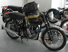
1951 rigid model Alloy MAC
Answer: “The question of changeover was dictated by two considerations. In the first place, the light-alloy head is a far easier machining proposition and thus allows the production of cylinder-head assemblies at a greater rate than was possible with the old design. The construction is an easier job, and it is a more up-to-date arrangement.
“When the original M-type of engine was designed, enclosure of the valve gear with air-cooled engines was not
widely used, and there was very little known about the subject. Casting a one-piece head would have been possible at that time, but tit was thought that to cast a large valve-spring chest on top of a cast-iron head would lead to troubles. Hence our original scheme of using thin steel cups and separate rocker boxes. It would, of course, have been possible to use this new one-piece design while retaining a cast-iron head, but obviously, a light-alloy head is much better from the point of view of good cooling and general weight reduction. The use of a light-alloy cylinder barrel follows automatically. In fine, the basic reasons for making the change were to bring the model right up to date and to reduce machining difficulties as far as was practicable.”

1954 US model Alloy MAC
Question: “The new cylinder employs very deep fins; does this mean that you subscribe to the theory that it is better to get heat right out of the air-stream and that it is better than trying to get moving air circulating around the barrel at the root of the fins?”
Answer: “Quite honestly, with this type of engine, it does not matter one way or the other. The real reason was to get away from the ‘skinny’ 1932
look and thus to have an engine which looks bigger. Appearance is improved by a nicer balance with the remainder of the machine. There is some slight advantage from having an increased fin area but, I repeat, the primary reason was to get the machine proportionally right aesthetically.”
Question: “Would you tell me what is the pitch of the cylinder fins and whether there is any point of interest in connection with the fin shape?”
Answer: “The pitch is 3/8 in. There is nothing unusual about the fin shape and no point of interest arises.”

1956 Alloy MAC
Question: “In the KTT engine, the silicon aluminium-alloy jacket, with its very deep fins, is cast on the nickel iron barrel which has a corrugated outer wall. The barrel is, I believe, heated and placed in the mould before alloy is poured. Would you like to explain the advantages of each of these systems-this on and the new one?”
Answer: “Well, the real underlying answer is that at the time the KTT barrel was produced, there were only two ways of obtaining a composite barrel. One of these was the method adopted for the works’ racing machines: that is to say, a fully machined liner was shrunk into the machined bore of a light-alloy jacket.
mentioned. Nowadays, both have been out-moded by the very up-to-the-minute Al-Fin process used on the MAC. Besides being more modern, the AL-Fin barrel has the advantage of a much better heat transfer.”
Question: “Have any changes been made to the bottom half of the engine at all since it was first introduced? If the answer is ‘No’ and the flywheel inertia was scientifically correct for the two-fifty engine, I should have thought that flywheels of greater diameter would have been necessary for the larger engine.”
Answer: “The answer to the first part of the question is ‘No’. But in fact, the two-fifty had very heavy flywheels that were rather heavier than they needed to be, with the result that the MOV engine was extremely smooth. Owing to the decision merely to increase the stroke it was impossible to inveigle flywheels of greater diameter into the existing crank case, in spite of the theoretical advantage. In any event, and I think you will agree, the standard flywheels are perfectly adequate for this particular engine.”
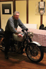
 The late Ron Owen, Australian VOC stalwart aboard his beloved "Alloy MAC", Aust.Nat.Velo Rally, Bright, Victoria
High Safety Factor
Question: “And the big-end……..? Inertia and centrifugal loadings must be greater with the three-fifty than they were originally---and they are possibly now greater again with the light-alloy engine, because of the increased power output.”
Answer: That is quite correct, the loading on the big-end is much greater with the three-fifty ---but it is a different big-end. This one is the same dimensionally as that fitted to our three-fifty racing machines. The safety factor, accordingly, is extremely high.”
Question: “I cannot remember ever having seen a full technical description of the flywheel assembly. Would you describe the assembly to me?”
Answer: “The flywheels themselves are 0.25 per cent carbon-steel forgings. The timing-side mainshaft is 3 per cent nickel steel, oil-hardened, and the driving-side shaft is 3 per cent nickel steel, case hardened. Both shafts are pressed into taper holes in the flywheel centres and are pegged. As you no doubt know, the crankpin is of two-piece construction, with the central portion which carries the nuts made of 3 ½ per cent nickel steel, oil-hardened and a separate roller track made from 1 per cent carbon chrome steel.”
Question: “Arising from that would you explain first why you oil-harden the timing-side shaft and case-harden its opposite number, and, secondly, why you favour having separate shafts and wheels? Could the flywheels and shafts not be forged as single units?”
Answer: “The reason for case-hardening the driving shaft is that it is splined to locate the shock-absorber sleeve. In this case, the shock absorber works directly on the mainshaft which must obviously be given a case to minimize wear. Regarding the second part of your question, it is, of course, possible to have the axles in one piece with the flywheels. In this particular instance, however, there are several objections.
“One of these is that, as I have just said, it is necessary to case-harden the driving shaft, and doing this with a shaft that is in one piece with a flywheel is almost an impossibility. Thus, the decision made to use a separate shaft on one side, there is no reason for using an integral shaft on the other. Equally important, however, is that by using separate components one can select the type of steel which has the best properties for each particular job. The 0.25 per cent carbon steel in which the flywheels are forged would be unsuitable for the shafts.”
Question: “Why do you favour using a separate roller track for the crankpin?”
Answer: “Because it is a much easier machining proposition. If we used a one-piece pin --- as we do on the KTT --- it would mean that it would have to be manufactured from a case-hardening steel. It is essential, as you well know, to have a case-hardened roller track, but the shanks have to be left soft because of strength considerations. Therefore, the use of a one-piece pin would mean that machining and hardening processes would be unnecessarily complicated; it would involve a lot of handling and increased production time --- and, therefore, increased cost.
“The sleeve, incidentally, is pressed on the pin in an ordinary mandril press and ground finally to size after being pressed on; it is, of course, ground before and after hardening, both on the periphery and in the bore. The final operations are to the roller track and side faces.”
Crankcase BreathingQuestion: “I note that the crankpin nuts are not locked. Is this because you feel that additional locking ‘safeguards’ are unnecessary?”
Answer: “Yes. The real answer is that provided the hexagon faces are square and flat, and they are put up to the correct degree of tension, they will never come loose. We used to lock the nuts with a grub screw, but the immediate question to that is, ‘What locks the grub screw? Putting a centre-punch indentation on the end of a shaft or pin is an excellent means of locking a nut in certain circumstances – but not in this particular case.”
Question: “Would you describe, please, how crankcase breathing is achieved and why you use this particular system?”
Answer: “Breathing is achieved through a hole in the middle of the driving shaft. This leads to a cross hole which mates up with a recess in the engine sprocket, and the gases
are discharged through slots in the sprocket. The reason for our using this particular type of breather is that if any oil is thrown out with the discharges gases, it helps to lubricate the engine sprocket. Finally, of course, the oil is thrown out to the chaincase, where it assists in primary chain lubrication.”
Question: “The connecting rod, I believe, is manufactured from a 3 ½ per cent nickel steel, heat-treated to 50-60 tons per square inch tensile strength. What is its length between the centres in relation to the stroke, and has the figure any special significance?”
Answer: “The stroke is 96mm or 3.779in. The connecting rod measures 6.875in and is, therefore, 1.82 times the stroke. The figure has no special significance. I have found no great variation when using either long connecting rods or short ones.”
Question: “To what extent is the reciprocating weight balanced?”
Answer: “70 per cent. Incidentally, each flywheel is individually balanced, with the result that each flywheel assembly is balanced to perfection.”
Question: “Returning to the timing gear, is there anything unusual about the tooth form?”
Answer: “Yes, there is something. In the first place the teeth are of every fine pitch and, of course, as we have already remarked, they are helical cut instead of being the more usual type of spur pinions.”
Question: “The reason you use helical gearing is, presumably, because you want to ensure mechanical quietness. But in the L.E. Velocette you use spur gears accurately machined by modern methods, are just as quiet as helical gears. It is not a fact that spur gearing in this case would be as quiet and yet prove less expensive?”
Spur or Helical Gears?
Answer” “I would not go so far as to say that your pinions are less expensive than helical ones are, but the new methods of machining spur gears have been developed since the MAC was originally designed. While we could today produce spur pinions for the MAC in the same way as we do those for the LE, we have no wish to make a change, thus introducing a service problem, at this stage.”
Question: “Do you make any provision for adjusting gear centres?”
Answer: “The intermediate gear centre spindle is capable of being moved to adjust the centre distance of the gears. Thus, on assembly, we can produce backlash in the timing pinions to a minimum. Incidentally, the gear pinion material is 3 per cent nickel case-hardening steel, which is given a light case. We use this particular material because the high tensile strength of a nickel steel is necessary in view of the very small gear teeth. In the interests of quietness again, the magneto pinion is made in Tufnol. We have a hunting tooth in the intermediate pinion so that wear is evenly distributed among the teeth.”
Question: “Does the tooth form compensate for variation between the centres, due to expansion and contraction of the crankcase?”
Answer: “As with most involute gear teeth, it is possible to operate them on centres other than the theoretically correct ones, so there is no special compensation --- for none is necessary.”
Question: “Your cam-wheel arrangement is unusual.. The cams, which are manufactured from case-hardening mild steel, have an integral boss which is a press fit in the pinion bore. The assembly is plain-bushed and rotates on a stationary shaft. Would you please explain why you use this system in preference to the more orthodox one?”
Answer: “It is easier to maintain correct gear centres by this method and, in addition, it is just about the only system that one can use for the moveable intermediate gear centre.”
Question: “Instead of the push-rods being operated through straight tappets, the MAC engine employs a system of cam followers, or, as you call them, bottom rockets. Has your system any real advantage over the other one?”
Answer: “If we used straight tappets with this type of cam, valve operation would be noisier. Our method is used chiefly with a view to achieving the maximum degree of operational quietness. Were we to alter the cam design we could, of course, obtain just as quiet running in conjunction with straight tappets. Indeed, broadly speaking, it is true to say that with modern knowledge and production methods, it is possible to make almost any type of valve gear quiet.”
Question: “The valve seats, I note, are of austenitic iron, shrunk in as on the KTT. But on the racing engine, different materials are used for the inlet and exhaust seats. Would you explain the reason why the difference does not appear on the MAC unit?”
Answer: “The iron used for both MAC valve seats is similar to that used for the inlet seating on the racing engines. But, owing to the much less arduous conditions under which the MAC engine works, it is not necessary to provide an aluminium-bronze seat for the exhaust valve. Another very important factor is that austenitic iron is much more hardwearing than aluminium-bronze. A point here is that the KTT engine is likely to be worked on much more frequently than the MAC!”
 Question:
 “Can you tell me if the choke diameter was decided upon with a view to high performance or good power at low revs, or, as with all design problems, is it a compromise between the two?”
Answer: “It is compromise between the two. One aims to get as good power output as possible at the top end without spoiling the power at low revs; and, of course, the reverse holds good. It is a compromise to obtain the best possible performance at both ends.
Question: “The rockers operate in separate DTD 424 light-alloy brackets. Could these brackets not have been incorporated with the rocker posts in the head castings, since there would then, I should have thought, have been even greater rigidity than at present? And would you explain why it has not been necessary to line the rocker housings with some form of hearing material?”
Bearing Pressures Low
Answer: “The reason is that in the original design of the engine, the rocker bearing surface was made of such ample proportions that the bearing pressures were already down to a very low figure, thus permitting the rockers to be run directly in the aluminium rocker box, avoiding, again, separate components. When the engine was redesigned with a light-alloy head, similar rockers were used, which meant that we could operate them in light-alloy housings quite successfully. The housings could not be incorporated in the head casting, since that would render two of the cylinder head studs inaccessible. It would also make the machining of the housings very difficult.”
Question: “Are the bearings split purely because of considerations of ease of assembly and dismantling?”
Answer: “They are split because it is the only way of getting a bearing on that particular design of rocker. The use of solid bearings would mean that a two-piece rocker construction would be essential. The disadvantages of that are obvious: there would be more component parts to machine and there would be, also, the possibility of slack developing between the two components of the rocker.”
Question: “And the power output …?”
Answer: “It is approximately 15 b.h.p. at 5,500 r.p.m. We make no attempt to obtain a higher power output although we have done so by tuning on special occasions. We have what we believe to be an excellent compromise, bearing in mind the poor quality of the fuel in Great Britain and the high quality obtainable in some overseas countries. The engine is so arranged that it will run on any of these fuels with a high degree of efficiency.”

Left click on images to enlarge.
 photocopied and pasted onto cardboard pages, making up a folder and from there I further photocopied into files to share with others... so I'm going to run a series from them, not in any particular order and this next lot are from The UK Velocette Owner's Club magazine "Fishtail", a sheet supplied in the past by Ivan Rhodes, Veloce Ltd and Alpha Bearings Ltd, Dudley, West Midlands, UK, "MotorCycling".........


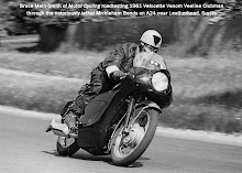
 Bruce Main-Smith on the main straight.....
 Bertie Goodman flat out on the back straight.......
 Pierre Monerett pushs off for a night stint.......


 First Machine in the World to Average the Ton for a Day
 The crankshaft assembly runs on Timken taper roller main bearings; it has an Alpha big-end with 18 caged 3/16” x 9/16” rollers.